TF3MA, Sun Sep 8 11:29:37 GMT 2002
13.8V 25Amp linear power supply
Şessi síğa hefur veriğ heimsótt  sinnum síğan 7. Júní 2003
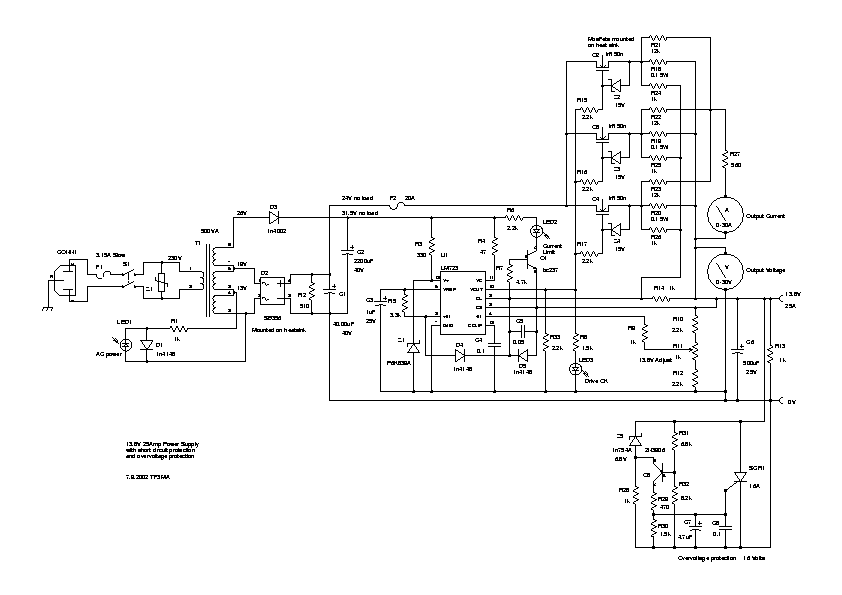
- This is my 13.8V 25Amp power-supply. With over-current (26 Amps) and
over-voltage (16 Volts) protection.
- Uses fold-back current limiting.
- Short circuit current is around 8 Amps.
- Uses 3 (or 4, which is better) IRF150n power MOSFETs as pass transistors.
LM723 can drive the MOSFETs directly.
- Needs big heat-sink, 1.2 C/W for the FETS and bridge rectifier, or forced
air cooling.
- Yes, the MOSFETs need equalizing resistors (0.1 Ohm 5 Watt) if they are
not closely matched. Short circuit current of 8 Amp must be divided between
the 3 MOSFETs, as the total power dissipated is 160 Watts. Better is to use 4
MOSFETS's to lessen the stress during short circuit.
- Power supply
schematic, pdf(12k))
Circuit details
I got the transformer from an old heater controller.
Any transformer can be used, it has to provide about 19V RMS at the rated
current. Extra transformer may be needed for the 30V supply for LM723 regulator.
The bridge rectifier is a 35Amp type and the 40.000uF capacitor is computer
grade, I used 3 12.900uF 40V surplus caps.
The LM723 regulator is used to
control the 3 or 4 MOSFETs, I used MOSFETs instead of bipolar transistors as the
MOSFETs can be driven directly by the LM723. The gates of the MOSFETs are
protected by 15V zener diodes. 0.1 Ohm resistors are used to equalize the
current between the MOSFETs and also to for current sensing. Fold-back current
limiting is done by R5 and D4 which provide extra current into R14 when the
output voltage is under VREF, and thereby lower the current limit set by the 0.1
Ohm resistors.
The output voltage is set by R11 and should be set to 13.8V.
3 led indicator are used, one for AC power, one for current limit indication and
one for monitoring the VOUT from LM723.
The crowbar circuit is for
over-voltage protection and fires at about 16 Volts. The voltage is sensed by
R31 and R32 and compared to the reference voltage provided by zener diode Z5
which is 6.8 V.
The 230V MOV is used to suppress any spikes on the 230V AC
line. Two fuses are used, 3.15 Amp Slow for the AC and 20 Amp for the DC.
The P6K839A is a 36V zener voltage suppressor, any 1W 36V zener can be used
instead, it is for protecting the LM723 which has max voltage rating of 40V.
73 de TF3MA
Schematic diagram drawn using gschem