|
An Amateur Radio Power Supply 13.8V
30-40A with short circuit protection - all you need to run the most
common 100-200W Amateur Radio transceivers...!
- Foreword
- Functions
- Project
schematic, PCB layouts and data sheets
- Pictures
My
homebrewed 13.8V 30-40A primary Power Supply, with built in short
circuit protection, build on POWER FET transistors.
Foreword
This is the primary Power Supply
for my Amateur Radio Shacks transceiver equipment. The Power Supply
is build around the LM723 controller and four BUZ24 (or IRF150)
power N-Channel FET transistors. FET transistors are used because of
the simplicity of controlling the current through these transistors,
it's simply voltage controlled, and because of the low power
consumption of the controller board. The Power Supply is initially
based on ideas from TF3MA.
Functions
-
Project
schematics, PCB layouts and data sheets
Pictures
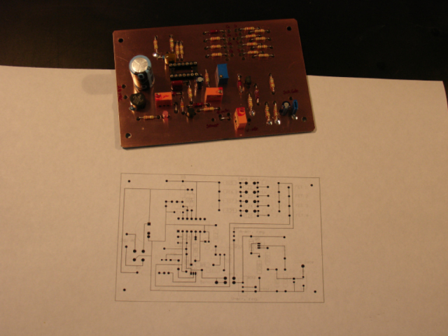
The Printed
Circuit Board (PCB) and the layout
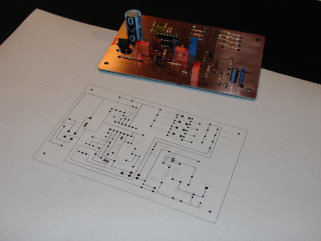
...from
another angle
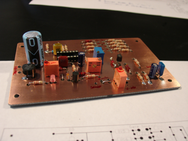
...a close up of
the controller PCB
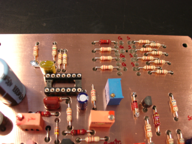
Here
are the holes for connection to the four FET's gate and
source.
The FET's drain
is connected directly to the '+' pole of
the 6 x 10.000
electrolyte capacitors. The 15V zener diodes,
between source and
gate, are not mounted when this picture
has been
taken.
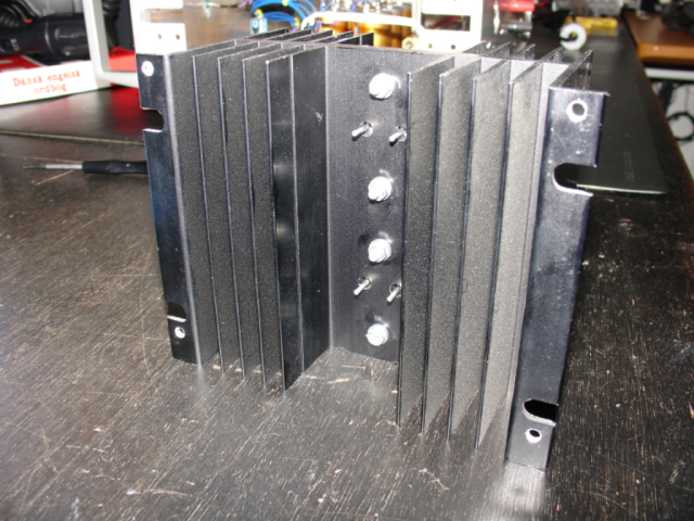
Mounting
two of the four BUZ24 FET's at one of the two
heat sinks. All
four FET's are isolated from the heat sink
by slices of silicone
between the FET's
and the heat sink and
small pieces of plastic between the screws
and the heat sink.
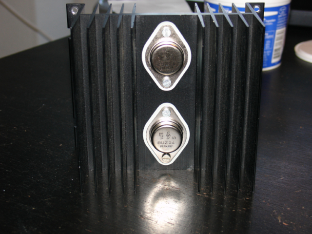
Two FET's mounted
at the rear of the heat sink
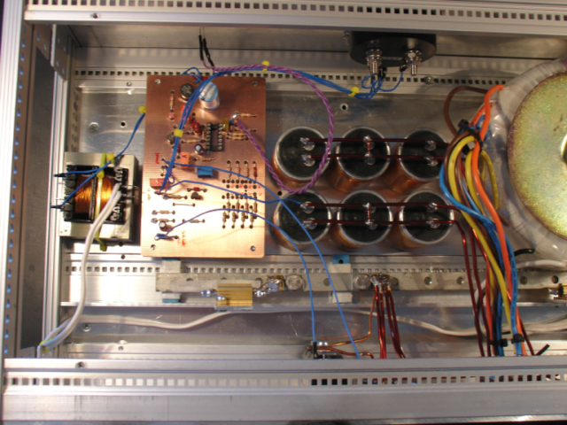
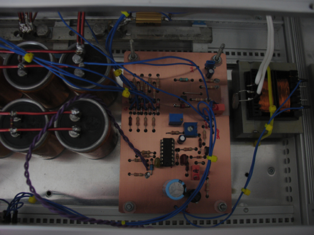
An
inside look at the Power Supply. At the left is a transformer
for powering the controller board next to it. In the middle
are the 6 x 10.000 uF electrolyte capacitors. At the right is a
part of the heavy duty ring transformer.
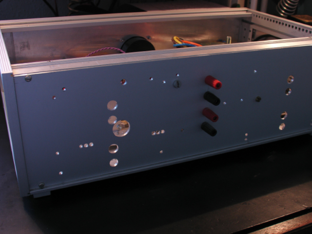
A look at
the rear of the second hand chassis of my Power
Supply - before
mounting of the two heat sinks loading
two FET's
both.
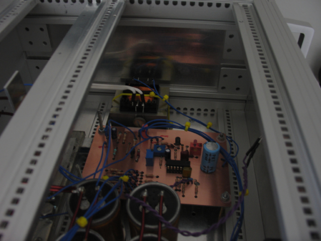
A look inside the
Power Supply from another angle...
...yet another
picture from the inside...
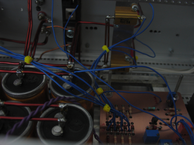
The two power
resistors in the back are two of the 0.1 ohm
resistors connected to each FET's
source.
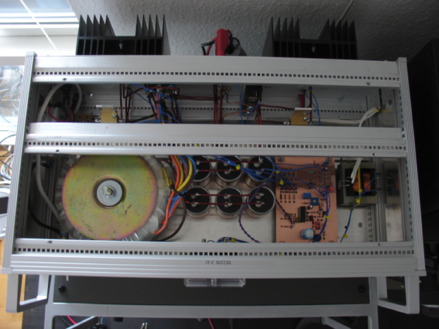
An overview
of the inside of the Power Supply
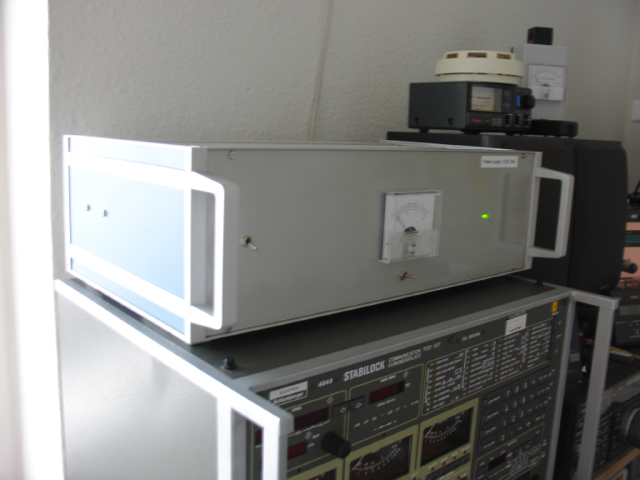
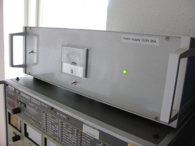
The front of the
Power Supply. Switch S2 is in amps and the
Power Supply is not
loaded in this situation - that's why
the meter isn't
showing anything.
Another picture of
the front of the 13.8V 30-40A Power
Supply using
N-Channel FET power transistors
| 