1300 V HV Supply
(HV supply for FRINEAR-400 RSGB's RadCom Apr 1995)
TRANSFORMER
At present it is not so easy to obtain correct high-voltage transformers. The problem is solved here by using a high-power isolation-transformer that must be of suitable rating to handle the wattage and heavy current involved in the following circuit.
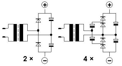
Doubling or quadrupling rectified AC-voltage
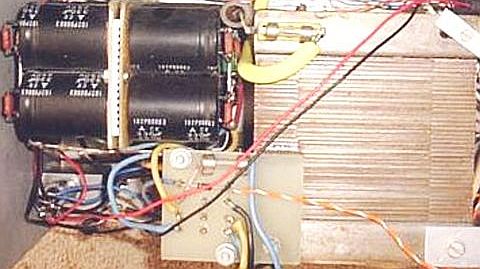
With a doubling or quadrupling circuit, adequate high voltage can be delivered. Series-connected modern electrolytics with large capacity and high voltage
(e.g. 470 μF/400 V) will give adequate smoothing and regulation during modulation peaks. They should be individually bridged by an equalizing resistance of 100 kΩ (2 W). For safety reasons and adequate cooling, it is better to have two 220 kΩ or three 330 kΩ resistors in parallel instead of one of 100 kΩ.VOLTAGE QUADRUPLER PSU
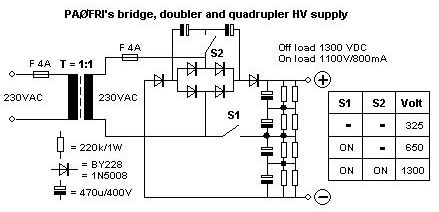
The special feature of this arrangement is that by means of two manually-operated swiches, the unit provides rectification, doubling and quadrupling of the AC-voltage delivered from a 1 : 1 mains isolating transformer. Shown here is a circuit with only 6 capacitors, 6 diodes and 2 switches. I have not seen this particular arrangement published previously, so I presume that I am the originator of this type of flexible PSU.
If you don't like the feature of adjusting with lowered voltage (soft-start, which prevents problems), the switches may be left out and the appropriate connections be made. The average voltage after quadrupling will be around 1150 V during SSB-transmission and around 1000 V with a constant carrier.
There is no soft-start delay in the power-supply as I presumed that the two switches and the internal resistances in the transformer suffice to limit the inrushcurrent.
ELECTROLYTICS
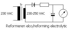
Electrolytics should have their dielectric reformed first, when they have not been used for a long time. This also holds for new on
es as the date of manufacture is seldom known. Reforming is done with a 200 – 300 V supply by charging the individual electrolytics through a 20 – 50 kΩ/10 W resistor. If the leakage current and voltage are stabilized (may take minutes), the supply voltage can be raised to the intended working voltage, which should be lower than the rated one. This reforming stage can be used for testing and selecting overaged electrolytics. After testing, the electrolytics should be discharged with a resistor. Normally, I use a 25 Ω/10 W resistor.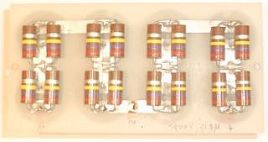
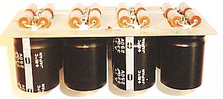
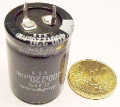
Electrolytic types (range 220 µF/400 V to 470 uF/450 V) for switched power supplies are suitable for this design.
![]()